A Beginner's Guide to Using Resistors in Circuits
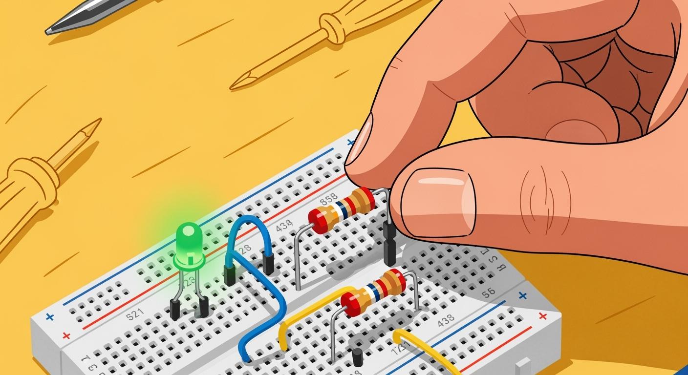
A resistor is a fundamental electronic component. You use this part for controlling the flow of current within a circuit.
Analogy Time! 💡 Imagine water moving through a pipe. A narrow section slows the water's flow. A resistor works the same way. It provides resistance to limit the flow of current.
This beginner guide covers essential resistor fundamentals. You will see how these tiny resistors protect your circuit. Learning about this resistor is a great first step.
Key Takeaways
Resistors control electricity flow in a circuit, like a narrow pipe controls water flow.
You can read a resistor's value using color bands or a multimeter.
Ohm's Law helps you choose the right resistor to protect parts like LEDs.
Resistors can be connected in series or parallel to change total resistance.
Resistors help transistors work correctly and prevent damage to other components.
How Resistors Work: A Beginner Guide
You now know a resistor is like a narrow pipe for electricity. This section explains the resistor fundamentals behind this idea. Understanding how resistors work is the key to using them correctly. You will see how these simple electronic components give you control over your projects. Learning how resistors work builds a strong foundation.
The Role of a Resistor
A resistor's main job is controlling the flow of current. Every material has some opposition to electrical flow, which we call resistance. How resistors work depends on a few factors:
Material: Some materials, like rubber, have very high resistance. Metals have very low resistance. Resistors use specific materials to get a precise resistance value in ohm.
Size and Shape: A longer, thinner wire has more resistance than a shorter, thicker one.
When you place a resistor in a circuit, it resists the flow of electrons. This process converts electrical energy into heat. This is how resistors work to manage energy. These resistors are essential for your circuit's safety and function.
Limiting Current and Dividing Voltage
You often use resistors to protect other components. Many parts, like LEDs, can be damaged by too much current. Placing a resistor in series with an LED limits the flow of current to a safe level. This is a primary example of how resistors work.
Resistors also help you divide voltage. When current flows through a resistor, a "voltage drop" occurs across it. This means the voltage on one side of the resistor is higher than on the other. You can use this effect to supply a specific, lower voltage to a part of your circuit. This is how resistors work to create different voltage levels from a single power source. By choosing the right resistor, you control both the current and voltage in your circuit.
Circuit Tip 💡 You can think of voltage as electrical pressure. A resistor reduces this pressure for components downstream, ensuring they get the correct operating voltage.
Resistor Schematic Symbols
When you look at a circuit diagram, you will see symbols for each component. Resistors have two common symbols. The one you see depends on where the diagram was made. The ANSI standard is common in the US, while the IEC standard is popular in Europe and Asia.
Resistor Type | ANSI Symbol (US) | IEC Symbol (International) |
|---|---|---|
Fixed Resistor |
Knowing both symbols helps you read any schematic. This is a key part of understanding how resistors work in diagrams.
Determining Resistor Value

You need to know a resistor's value to use it correctly. These tiny components don't have their value printed directly on them. Instead, you use a few simple methods to determine the value of a resistor. This section shows you how to find the exact value of your resistors.
Reading Resistor Color Codes
Most resistors use a system of colored stripes to show their value. You can figure out the resistor's value by reading the color bands from left to right. The last band, usually gold or silver, is the tolerance band and should be on your right.
Memory Tip! 🧠 You can remember the resistor color code order with a mnemonic: Bad Boys Run Over Yellow Gardenias Behind Victory Garden Walls. This stands for Black, Brown, Red, Orange, Yellow, Green, Blue, Violet, Grey, White.
Here is a chart for the resistor color code:
Color | Digit (Band 1 & 2) | Multiplier (Band 3) | Tolerance (Band 4) |
|---|---|---|---|
Black | 0 | 1 | |
Brown | 1 | 10 | ±1% |
Red | 2 | 100 | ±2% |
Orange | 3 | 1k | |
Yellow | 4 | 10k | |
Green | 5 | 100k | ±0.5% |
Blue | 6 | 1M | ±0.25% |
Violet | 7 | 10M | ±0.1% |
Grey | 8 | 100M | |
White | 9 | 1G | |
Gold | 0.1 | ±5% | |
Silver | 0.01 | ±10% |
For a common 4-band resistor, reading the color bands is simple:
First Band: This is the first digit of the value.
Second Band: This is the second digit of the value.
Third Band: This is the multiplier. You multiply the first two digits by this number.
Fourth Band: This shows the tolerance, or how accurate the resistor's value is.
Using a Multimeter
A multimeter gives you a direct reading of a resistor's value. It is the most accurate way to check resistors.
Set your multimeter to the resistance mode, often marked with the omega symbol (Ω).
Touch one probe to each lead of the resistor.
The screen will display the resistor's value.
If your multimeter shows "OL" or "1", it means "Over Limit." The resistance of the resistor is too high for the range you selected. You just need to turn the dial to a higher resistance setting.
Understanding Resistance Units
You measure resistance in a unit called the ohm (Ω). The value is named after Georg Ohm, who discovered the relationship between voltage, current, and resistance. Because resistor values can be very large, you will often see prefixes:
A kiloohm (kΩ) is 1,000 ohms. A 2.2kΩ resistor has a value of 2,200 ohms.
A megaohm (MΩ) is 1,000,000 ohms.
You will notice that resistors come in specific, common resistor values, like 220Ω or 4.7kΩ. These standard values come from the E-series system, which ensures a good selection of resistor values are available for any project. This knowledge of resistor fundamentals helps you select the right component.
Practical Application: Lighting an LED
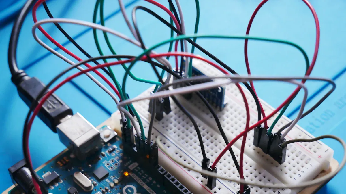
Theory is great, but putting it into practice is where the real learning happens. You will now build your first simple circuit: lighting a Light Emitting Diode (LED). This project is a perfect way to see how resistors work. These hands-on applications will solidify your understanding. This is one of the most common resistor applications for beginners.
Why an LED Needs a Resistor
You might wonder why you cannot connect an LED directly to a battery. An LED is a type of diode, and it is very sensitive to the amount of electrical current it receives. It does not have much internal resistance to protect itself. If you connect an LED directly to a power source, a few things will happen:
The LED will be over-driven by too much current.
It will become very bright for a short time.
It will then flicker and burn out, sometimes in just a few moments.
Sudden spikes in current when you turn the power on can also damage an unprotected LED. Using resistors prevents this damage. A resistor placed in the circuit limits the current to a safe level. This ensures your LED operates correctly and lasts for its full lifespan.
Using Ohm's Law
To figure out which resistor you need, you will use a fundamental rule of electronics called Ohm's Law. A German physicist named Georg Simon Ohm discovered this relationship. In 1827, he published his findings from experiments where he measured voltage and current through wires. He found that the current flowing through a conductor is directly proportional to the voltage applied to it.
This relationship is described by a simple formula:
Ohm's Law:
V = I * R
Let's break down what each letter means in your circuit:
V (Voltage): This is the electrical pressure from your power source, measured in Volts (V). Think of it as the "push" that moves electricity.
I (Current): This is the flow of electricity, measured in Amperes (A). This is what you need to limit for your LED.
R (Resistance): This is the opposition to the current, provided by your resistor and measured in Ohms (Ω).
You can rearrange this formula to solve for any value. For example, if you know the voltage and resistance, you can find the current (I = V / R). If a hairdryer operates at 220 volts and draws a current of 11 amperes, you can find its resistance (R = V / I = 220V / 11A = 20Ω). This law is essential for many electronics applications.
How to Select the Right Resistor
Now you can use Ohm's Law to select the right resistor for your LED. Let's work through a common example.
Your Goal: Power a standard red LED using a 9V battery.
Your Components:
Power Source (Vs): A 9V battery. So,
Vs = 9V.LED: A standard red LED. LEDs have two key ratings you need from their datasheet (or a standard value if you don't have one).
Forward Voltage (Vf): This is the amount of voltage the LED "uses up" when it's on. For a red LED, this is typically around 2V.
Forward Current (I): This is the ideal amount of current for the LED to be bright and safe. A common value is 20mA, which you must convert to Amperes for the formula:
20mA = 0.02A.
Here is the step-by-step calculation to select the right resistor:
Find the Voltage for the Resistor: The resistor needs to drop the leftover voltage that the LED doesn't use. You find this by subtracting the LED's forward voltage from the source voltage.
Voltage for Resistor (Vr) = Source Voltage (Vs) - LED Forward Voltage (Vf)Vr = 9V - 2V = 7VSo, your resistor needs to handle 7V of the total voltage.
Calculate the Resistance: Now use Ohm's Law to find the resistance needed. You know the voltage for the resistor (7V) and the current you want for the circuit (0.02A).
R = V / IR = 7V / 0.02A = 350Ω
Choose a Standard Resistor: You will not find a 350 ohm resistor. Resistors come in standard values. You should choose the next highest standard value, such as 390Ω. Using a slightly higher value is safer because it will allow a little less current to flow. A 330Ω resistor would also work well.
Building the LED Circuit
It's time to build the circuit! You will need a few components.
A power source (like a 9V battery with a connector)
One LED
The resistor you selected (e.g., 390Ω)
Jumper wires
Before you connect anything, you must identify the LED's legs. An LED only works in one direction.
LED Polarity Tip 💡
Anode (+): The positive leg. This is the longer of the two legs.
Cathode (-): The negative leg. This is the shorter leg. It is also next to a flat edge on the LED's plastic casing.
The positive anode must connect toward the positive side of your power source, and the negative cathode must connect toward the negative side. The resistor can go on either side of the LED in this simple circuit.
To guide you, here is a schematic diagram and a photo of the final circuit on a breadboard. The schematic shows the electronic theory, while the breadboard photo shows you how to physically connect the parts. Following these diagrams will help you successfully build your first LED circuit and see your resistor in action.
(In a real blog post, a schematic image and a breadboard photo would be inserted here.)
Beyond the Basics: Common Resistor Configurations
You now know how to use a single resistor. Let's explore how you can combine resistors to achieve more control in your circuit. These common configurations open up new possibilities for your projects. Understanding these different types of setups is a key skill.
Series and Parallel Resistors
You can connect multiple resistors together to get a new total resistance value. The two basic types of connections are series and parallel.
Series: You connect resistors end-to-end in a single line. The total resistance is the sum of all the individual resistors. For example, a 100 ohm resistor and a 200 ohm resistor in series give you 300 ohms of total resistance.
Parallel: You connect resistors side-by-side. The total resistance is always less than the smallest individual resistor value.
Knowing these two types of connections helps you create custom resistance values when you do not have the exact resistor you need.
Creating a Voltage Divider
A voltage divider is a simple circuit that turns a large voltage into a smaller one. You can build one using two resistors in series. This setup is useful when you need to supply a specific, lower voltage to a component.
Voltage Divider Formula ⚙️ You can calculate the output voltage with this formula:
Vout = VS * (R2 / (R1 + R2)).
VSis your source voltage.
R1andR2are your two resistors.
Voutis the new, lower voltage.
By choosing the right resistors, you can precisely control the output voltage. This is one of the most common applications for different types of resistors.
Resistors and Transistors
Resistors are essential partners for transistors. A transistor can act like an electronic switch, and resistors help it work correctly. You will often see two types of resistors used here: a pull-up resistor and a pull-down resistor.
A pull-up resistor connects a pin to the positive voltage source. It keeps the pin in a HIGH state until it is pulled LOW.
A pull-down resistor connects a pin to ground. It keeps the pin in a LOW state until it is pulled HIGH.
These types of resistors prevent a pin from "floating" in an unknown state. You also use a resistor to limit the current going into a transistor's base, which protects it from damage. These different types of resistors ensure your transistor-based circuit is reliable.
You now understand what resistors do. You can find a resistor's value. You can also use the ohm unit to calculate the correct resistor value for your circuit. These skills help you confidently choose the right resistor value. You can use resistors to protect your components. Finding the correct value is a key step. You have the knowledge to select a resistor with the right value. These resistors have a specific value.
Now, go build something great! 🚀 Find the value of your resistors and bring your ideas to life. This will help you find the correct value.
FAQ
What happens if I use the wrong resistor?
Using a resistor with too low a value can damage your components. It allows too much current to flow. Using a resistor with too high a value will make your circuit work poorly. For example, your LED might be very dim or not light up at all.
Can I put a resistor in backwards?
Most common resistors are not polarized. You can connect them in either direction in your circuit. They will work the same way no matter which way you orient them. This makes them very easy for you to use in your first projects.
What does a resistor's power rating mean?
The power rating tells you how much heat a resistor can handle safely. This rating is measured in Watts (W). For most low-power circuits, like lighting an LED, a standard 1/4 Watt resistor is perfectly fine. You must choose a higher wattage for high-power applications.
Why do some resistors have five color bands?
Resistors with five bands are high-precision resistors. The first three bands represent digits, the fourth is the multiplier, and the fifth is the tolerance. You use these when your circuit requires a very exact resistance value. Standard four-band resistors are great for most projects.