Is 2N3906 a PNP Version of 2N3904? Let's Compare
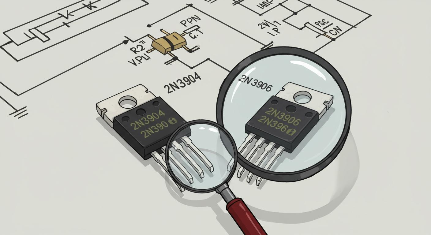
The short answer is yes. The 2N3906 is the complementary PNP counterpart to the 2N3904 NPN transistor. The 2N3906 PNP transistor operates with an opposite voltage and current flow. However, both this transistor and its NPN twin share nearly identical electrical characteristics. The 2N3906 is a classic "jellybean" component. It excels in general-purpose low-power amplification and basic switching applications. The 2N3906 handles a specific voltage and current, making this PNP transistor versatile for many projects.
The 2N3906 transistor's reliable current and voltage characteristics support countless amplification and switching applications, making the 2N3906 a staple for general-purpose low-power amplification.
Key Takeaways
- The 2N3906 is a PNP transistor. It is the opposite of the 2N3904 NPN transistor.
- The 2N3906 works best for high-side switching. It sends power to a device.
- The 2N3904 works best for low-side switching. It connects a device to ground.
- Both transistors are good for making sounds louder. They work together in some circuits.
- You cannot swap a 2N3906 for a 2N3904. They need different power setups.
PNP vs. NPN Fundamentals
Understanding the core difference between a PNP and NPN transistor is key to using them correctly. The 2N3906 and 2N3904 are perfect examples of these opposite types. Their internal structure dictates how they control current in electronic circuits. Both are a type of bipolar junction transistor, but they operate with opposite voltage polarities. This difference is fundamental to their applications.
The 2N3906 PNP Transistor
The 2N3906 is a PNP bipolar junction transistor. Its physical construction features a layer of N-type semiconductor material sandwiched between two P-type layers. This bipolar structure defines its behavior.
In a PNP transistor like the 2N3906, the majority charge carriers are "holes" (the absence of electrons). The flow of these holes constitutes the main electrical current.
The 2N3906 transistor controls current from its emitter to its collector. A small current leaving the base terminal turns the transistor "on". This typically happens when the base voltage is pulled lower than the emitter voltage. Grounding the base pin forward-biases the 2N3906, allowing a larger current to flow. This makes the 2N3906 ideal for high-side switching applications. The bipolar transistor acts like a closed switch in this state. Applying a positive voltage to the base stops the current, turning the 2N3906 off.
The 2N3904 NPN Transistor
The 2N3904 transistor is the NPN bipolar counterpart. Its construction is the inverse of the 2N3906. It has a P-type layer sandwiched between two N-type layers. This bipolar design means it uses different charge carriers. In an NPN transistor, electrons are the majority charge carriers that create the primary current flow.
To activate the 2N3904 transistor, a small positive voltage and current must be applied to its base. This forward-biases the base-emitter junction, allowing a much larger current to flow from the collector to the emitter. This behavior is essential for its use in low-side switching applications. A proper bias circuit ensures the transistor performs efficiently. The bipolar device functions as an open switch when the base voltage is removed.
Schematic Symbol Differences
The schematic symbols for NPN and PNP transistors are very similar, but one small detail changes everything: the arrow on the emitter. This arrow indicates the direction of conventional current flow.
| Transistor Type | Emitter Arrow Direction | Mnemonic |
|---|---|---|
| PNP (2N3906) | Points In toward the base. | Points In Proudly. |
| NPN (2N3904) | Points Out, away from the base. | Not Pointing iN. |
This single difference in the circuit symbol is a critical reminder of the opposite voltage and current requirements for each bipolar junction transistor. Correctly identifying the symbol prevents errors when designing and building circuits. The arrow ensures you apply the correct voltage to the correct bipolar transistor for your applications.
Key Spec Comparison
While the 2N3906 and 2N3904 serve opposite functions, a look at their datasheets reveals just how closely their performance characteristics align. Their specifications are a near-perfect mirror image, confirming their status as a complementary pair. Understanding these key performance metrics is essential for selecting the right transistor for your applications.
Polarity and Current Flow
The most fundamental difference lies in their polarity and the direction of current. The 2N3906 is a PNP transistor, while the 2N3904 is an NPN transistor. This dictates how they behave in a circuit.
- In the 2N3906 (PNP), conventional current flows from the emitter to the collector. The transistor activates when its base voltage is pulled lower (more negative) than its emitter voltage.
- In the 2N3904 (NPN), conventional current flows from the collector to the emitter. This transistor turns on when a small positive voltage and current are applied to its base.
Despite these opposite electrical behaviors, their physical layout is conveniently identical. For the common TO-92 package, the 2n3906 pin assignment is Emitter-Base-Collector from left to right when viewing the flat side. The 2n3904 transistor follows the exact same 2n3906 pin assignment, which simplifies board design for complementary circuits.
Voltage and Current Limits
The absolute maximum ratings for voltage and current are critical specifications for ensuring a transistor's longevity. For the 2N3906 and 2N3904, these values are strikingly similar, differing only in polarity. Both transistors can handle a continuous collector current of 200 mA and have a power dissipation of 625 mW, making their performance characteristics suitable for many low-power applications.
| Specification | 2N3906 (PNP) | 2N3904 (NPN) |
|---|---|---|
| Collector-Emitter Voltage (Vceo) | -40 V | 40 V |
| Collector Current (Ic) | 200 mA | 200 mA |
| Power Dissipation (Pd) | 625 mW | 625 mW |
The key takeaway is that the absolute voltage and current handling capabilities are the same. The negative voltage for the 2N3906 simply reflects its PNP nature.
The 2N3906 transistor is also valued for its high-speed switching performance. This makes the 2N3906 an excellent choice for control circuits and signal processing applications that require rapid switching with minimal delay. Its low saturation voltage further improves its efficiency in switching applications.
DC Current Gain (hFE)
DC current gain, or hFE, measures a transistor's ability to amplify a small base current into a larger collector current. A higher gain means more amplification. The 2N3906 and its counterpart exhibit very similar gain characteristics. The performance of the transistor depends heavily on this gain. For both, the hFE typically peaks when the collector current is around 10 mA, with a gain value often falling between 100 and 300.
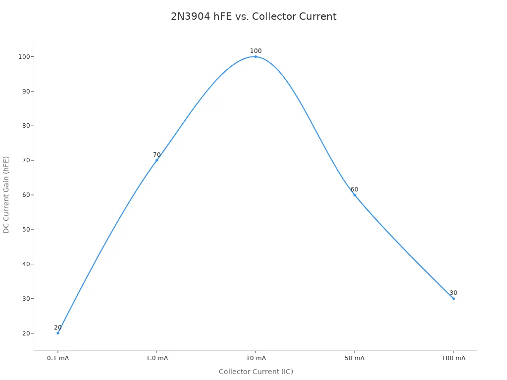
These gain specifications are measured under specific test conditions, usually with a collector-emitter voltage of 1.0V. The consistent gain performance across a range of currents makes the 2N3906 a reliable and predictable transistor for amplification and switching circuits.
Practical Applications of 2N3906 & 2N3904
The true value of the 2N3906 and 2N3904 transistors shines in their practical applications. Their complementary nature allows for elegant solutions in countless electronic circuits. These devices are staples in both hobbyist projects and mass-produced electronics. Their versatility covers everything from simple switching applications to more complex signal amplification. Many applications of 2N3906 and 2N3904 involve basic control and signal processing. You can find these transistors in common home appliances and television systems.
High-Side Switching with 2N3906
High-side switching is a common technique where the switch is placed between the positive power supply and the load. The 2N3906 is perfectly suited for these applications. It acts as a source for the current that powers the load.
To activate the circuit, a control signal pulls the base of the 2N3906 to a lower voltage, typically ground. This action allows a small base current to flow out of the transistor. This small current enables a much larger current to flow from the emitter to the collector, turning the load on. This method provides effective control over the load. The applications of 2N3906 often leverage this simple control mechanism.
This simplicity makes the 2N3906 a popular choice for many control circuits. The applications of 2N3906 in switching are widespread because of this easy implementation.
Low-Side Switching with the 2N3904
Low-side switching places the transistor between the load and the ground connection. The transistor's job is to sink current from the load to the ground, completing the circuit. The NPN 2N3904 excels in these switching applications.
A small positive voltage and current applied to the base of the transistor will turn it on. Microcontrollers, such as an ESP32, often provide this control signal from a GPIO pin.
- A HIGH signal (e.g., 3.3V) from the microcontroller reaches the base of the 2N3904 transistor.
- This action turns the transistor on.
- Current can now flow from the power source, through the load, and down through the transistor to ground.
This configuration is one of the most common applications of 2N3904. It provides simple and effective digital control over motors, LEDs, and relays.
This simple addition ensures the long-term reliability of your switching circuits. The control is direct and efficient for many low-power switching applications.
Basic Transistor Amplifier Circuits
Both the 2N3906 and 2N3904 are excellent for signal amplification. Their reliable performance makes them ideal for audio systems and other signal processing applications. One of the most classic circuits that demonstrates their synergy is the push-pull amplifier. This circuit uses the complementary pair to amplify an entire AC waveform.
- The 2N3904 (NPN) transistor handles the positive half of the signal. It turns on when the input voltage is positive.
- The 2N3906 (PNP) transistor handles the negative half of the signal. It activates when the input voltage goes negative.
Together, they "push" and "pull" the current to recreate the full amplified signal at the output. This is a fundamental design in audio driving circuits. However, a simple push-pull circuit can suffer from crossover distortion. This issue occurs when the input voltage is near zero, causing both transistors to turn off momentarily.
This clever use of a complementary pair is a cornerstone of analog electronics. It showcases how the opposite characteristics of the 2N3906 and 2N3904 create powerful and efficient circuits for amplification. These amplification applications are fundamental to electronics design.
The 2N3906 transistor is the essential PNP complement to the NPN transistor. The 2N3906 transistor handles negative voltage and current, while its twin uses positive voltage and current. This makes the 2N3906 transistor ideal for specific applications. The 2N3906 transistor excels in high-side switching applications. The 2N3906 transistor has a specific voltage and current rating. The 2N3906 transistor is a versatile PNP transistor. Its voltage and current capabilities make this transistor a must-have.
For maximum design flexibility, hobbyists should stock both transistor types. Use the NPN for low-side switching applications that sink current. Use the 2N3906 for high-side applications that source current. This ensures the right transistor, with the right voltage and current, is always available.
FAQ
Can I use a 2N3906 in place of a 2N3904?
No, you cannot directly substitute them. The 2N3906 is a PNP transistor, while the 2N3904 is an NPN type. They require opposite voltage and current polarities to operate correctly. A circuit designed for one will not work with the other without significant modification.
What are the main applications for these transistors?
These components have distinct roles.
- 2N3904 (NPN): Ideal for low-side switching, where it sinks current to ground.
- 2N3906 (PNP): Perfect for high-side switching, where it sources current to a load. Both are excellent for signal amplification applications.
Is the 2N3906 a good transistor for audio?
Yes, the 2N3906 is a solid choice for low-power audio circuits. Designers often use it in preamplifier stages and as part of a push-pull driver. Its predictable performance makes it a reliable component for basic audio amplification.
Why does the 2N3906 use a negative voltage?
The 2N3906 is a PNP transistor. Its internal P-N-P structure requires a negative base-to-emitter voltage to activate. This allows the main current to flow from the emitter to the collector. This behavior is fundamental to how all PNP devices function.